| Faceplate size | 63.5mm tall × 61.5mm wide |
| Flap positions | 4 (0°, 10°, 20°, 30°) via microswitches |
| Position indicator | SG90 micro servo (optional) |
| Materials | PLA or PETG (faceplate optionally ABS) |
| Connection | 4 × digital inputs + 1 × servo output |
| PRD board | PRD-NODE + PRD-BO-TRIMFLAPS breakout |
| Designed by | Chris Malcolm, Park Road Designs |
| Published | November 2025 |
Why microswitches?
Most Cessna 172 flaps lever designs found online use a potentiometer to set the flap position. In practice, getting the calibration exactly right — and keeping it there — turns out to be surprisingly difficult.
Investigating how the real Cessna 172 works was the inspiration here. The real aircraft uses microswitches to detect the flap lever position precisely. This design brings the same approach to the sim.
Four microswitches correspond to the four Cessna flap settings — 0°, 10°, 20°, and 30°. When the lever is moved to a position, the mechanism trips exactly one microswitch, registering that position as a digital button press in the sim. There is nothing to calibrate. It either registers or it doesn't.
An SG90 micro servo drives a flap position indicator pointer behind the faceplate, which moves to show the current flap setting as the sim data updates it — just like the real aircraft instrument.
The original design connected to an Arduino running MobiFlight. This guide also covers the recommended approach — connecting to a PRD-NODE + PRD-BO-TRIMFLAPS breakout board, which makes setup much simpler with no Arduino or MobiFlight needed.
Printing the parts
Download the .3MF file from MakerWorld using the link above and open it in Bambu Studio or your preferred slicer. All parts are included in the file.
PLA works for all parts and is the easiest to print. The designer used white PLA for most parts and black ABS for the faceplate. PETG is a good alternative to ABS for the faceplate if you have difficulty with ABS warping.
The file includes five versions of the indicator pointer with slightly different hole sizes. Print all five and trial-fit them on your servo spline — servo shaft dimensions vary between batches even for the same model number.
The faceplate is 63.5mm tall × 61.5mm wide. Cut the hole in your panel slightly larger — approximately 64 × 62mm — to allow the faceplate to slide through cleanly.
Additional parts to buy
Beyond the printed parts you'll need the following hardware and electronics. Total cost is typically under £15–20 depending on your source.
| Qty | Part | Specification | Notes |
|---|---|---|---|
| 4 | Microswitch with roller lever | Standard roller-lever microswitch | Must be the type with roller handle. Available from AliExpress — search "roller lever microswitch". Example listing. |
| 1 | Compression spring | ~5mm diameter × 15–20mm length | 5.5mm × 17.5mm was used in the original design — any spring around 5mm diameter will work. Hardware stores often sell singles for a few pence. AliExpress spring assortment. |
| 2 | M2.5 × 12mm screws | M2.5 × 12mm | Used to secure the cover plate. Buy an assorted M2.5 set — very useful for other builds too. AliExpress listing. |
| 1 | SG90 micro servo (180°) | SG90 or equivalent, 180° rotation | Drives the flap position indicator pointer. Comes with the small screws needed to mount it. Must be 180° — the 360° continuous rotation version will not work correctly. Available from AliExpress. |
| 1 | PRD-NODE + PRD-BO-TRIMFLAPS (recommended) | Park Road Designs PRD-NODE v1.0 + PRD-BO-TRIMFLAPS | Recommended — replaces the Arduino + MobiFlight setup. Plug the flaps lever into the TRIMFLAPS breakout board's FLAPS terminals. See PRD-NODE + PRD-BO-TRIMFLAPS section below. |
Assembly
Follow the steps below in order. Take your time with the spacer block orientation — it's the most common assembly mistake.
Three of the four microswitches press into the printed slots on the main body. The roller levers should face inward toward the centre of the mechanism. The fourth switch is installed later at a higher position using the spacer block.
The switches snap in and are held by the printed retention features — no glue needed at this stage.
Press the four spacer blocks into position over the microswitches. There are two types — spacer-block-A and spacer-block-B — and they must go in the correct positions.
The spacer blocks have thin locating pins that can snap if forced. Ensure correct orientation before pressing home. If a block won't seat easily, check the orientation rather than applying more force.
The fourth microswitch sits elevated above the others, mounted on top of one of the spacer blocks. This positions it at the correct height to be tripped by the lever mechanism at the 30° flaps position.
Assemble the swing arm from its printed parts. Place the compression spring loosely in position — do not compress it yet. The spring will be compressed into its final position in the next step.
Slide the assembled swing arm mechanism onto the main body, positioning it all the way away from the microswitches for now. The spring provides the return bias and detent resistance — it should not be compressed yet.
Place the cover plate on top and secure with the two M2.5 × 12mm screws. Do not overtighten — finger tight plus a quarter turn is sufficient.
Once the cover plate is in place, compress the spring by sliding the swing arm mechanism forward toward the microswitches until the central hole aligns ready for the bolt.
View the assembly from the side to confirm the spring is evenly compressed and the swing arm is correctly aligned. The printed bolt thread should be clearly visible below the main body.
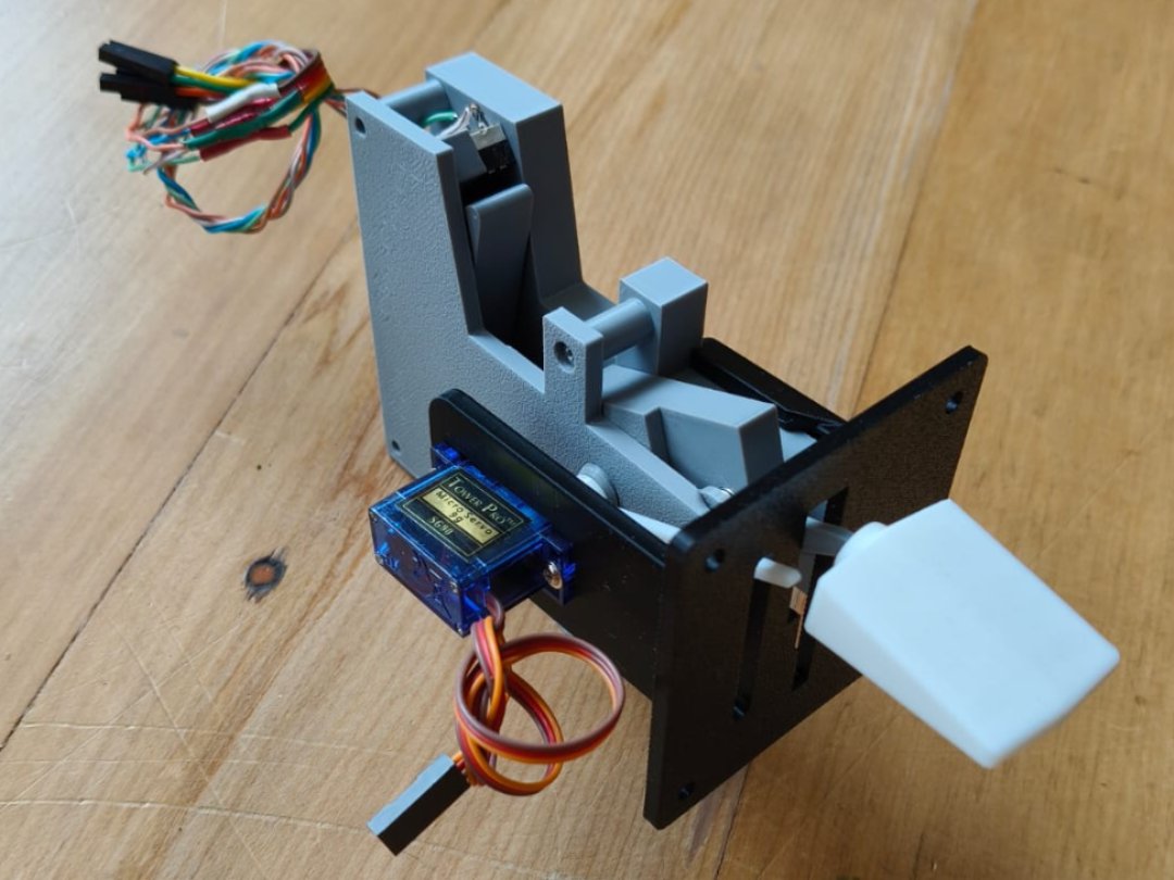
Mount the SG90 servo to the bracket using the two small screws that came with the servo. Orientation is important — refer to the assembly photo to ensure the servo is positioned correctly.
Trial-fit the five printed indicator pointers on the servo shaft spline and choose the tightest fitting one. Do not glue the pointer yet.
Insert the complete mechanism into the faceplate-and-brackets assembly. Thread the printed bolt through the central hole and tighten to secure the pivot.
Attach the handle to the threaded end of the lever arm.
You may need to remove the handle to adjust the mechanism during wiring and software setup. Only add a dab of glue once everything is tested and working to your satisfaction — gluing makes disassembly impossible.
Wiring
The electrical connections are straightforward — four switch signals, a common ground, and a servo connection.
How the switches work
Each microswitch is held closed by the mechanism in all positions except its own. When the lever reaches a microswitch's position, the roller lever is released and that switch opens.
This means in normal operation three switches are closed and one is open — the open one identifies the current flap position.
| Flaps 0° (up) | Switch 1 open, switches 2/3/4 closed |
| Flaps 10° | Switch 2 open, switches 1/3/4 closed |
| Flaps 20° | Switch 3 open, switches 1/2/4 closed |
| Flaps 30° (full) | Switch 4 open, switches 1/2/3 closed |
Switch wiring
Wire all four microswitches with a common ground — connect all COM terminals together and run a single GND wire. Each switch then needs a single signal wire from its NO (normally open) terminal.
With internal pull-ups enabled in firmware, a closed switch reads logic high and an open switch reads logic low.
Servo wiring
The SG90 servo has three wires — brown (GND), red (+5V), and orange (signal). Connect signal to a PWM-capable output pin and configure it to output a 50Hz servo signal (1ms–2ms pulse width).
The three microswitch terminals are COM (common), NO (normally open), and NC (normally closed). Connect GND to COM and the signal wire to NO. Leave NC unconnected.
Solder a short length of wire to each microswitch terminal before installing them in the printed body — access to the terminals is much easier before assembly. Use heat-shrink on each joint.
The servo indicator takes a little trial and error to calibrate. The position is driven by sim data (TRAILING EDGE FLAPS LEFT PERCENT) and mapped through an interpolation table. Start with 0 → 0° and 1 → 113° as the initial mapping and adjust from there to match your indicator pointer travel.
Connecting to PRD-NODE via PRD-BO-TRIMFLAPS
The recommended way to connect the flaps lever is via the PRD-BO-TRIMFLAPS breakout board plugged onto a PRD-NODE. The breakout board provides labelled 3.5mm pluggable screw terminals — just run four wires from the microswitches and three from the servo. No soldering to the NODE itself required.
The PRD-BO-TRIMFLAPS has 10kΩ pullup resistors and 100nF debounce capacitors already fitted for every switch input — no external components needed. The screw terminals are pluggable, so you can disconnect the wiring loom from the board without desoldering. The flaps section and trim wheel section are on the same board, so one NODE handles both.
Screw terminal connections
Connect to the FLAPS and SERVO1 terminals on the PRD-BO-TRIMFLAPS board.
| Wire from | Terminal on PRD-BO-TRIMFLAPS | NODE pin (internal) |
|---|---|---|
| Switch 1 NO (flaps 0°) | FLAPS — SW3 | D0 / PB2 |
| Switch 2 NO (flaps 10°) | FLAPS — SW4 | D1 / PB10 |
| Switch 3 NO (flaps 20°) | FLAPS — SW5 | D2 / PB11 |
| Switch 4 NO (flaps 30°) | FLAPS — SW6 | D3 / PB12 |
| All switch COM terminals (shared) | FLAPS — GND | GND |
| Servo signal (orange wire) | SERVO1 — SIG | SRV1 / PA8 |
| Servo power (red wire) | SERVO1 — +5V | +5V rail |
| Servo ground (brown wire) | SERVO1 — GND | GND |
The PRD-BO-TRIMFLAPS pullup resistors hold each switch input high. A closed switch pulls the line to GND (logic 0). An open switch reads high (logic 1). The open switch is the active flap position.
What the PRD-BO-TRIMFLAPS provides
The FLAPS connector is a 5-pin pluggable terminal (SW3, SW4, SW5, SW6, GND). SERVO1 is a 3-pin pluggable terminal (GND, +5V, SIG). The plug lifts out cleanly for maintenance — no desoldering needed.
Each switch input has a 10kΩ pullup to 3V3 and a 100nF cap to GND on the board. No additional components are needed on the switch side.
PA8 (SRV1, TIM1_CH1) runs at 50Hz. Prescaler gives 1MHz clock — Period: 20,000, Pulse: 1000–2000 (1ms–2ms). Map 0% flaps → 1000, 100% flaps → 2000. Fine-tune end points to match your indicator pointer travel.
Connecting with MobiFlight + Arduino
If you already have a MobiFlight setup with an Arduino Mega, the flaps lever integrates easily.
Switch configuration
Connect the four switch signal wires to digital pins on the Arduino. Wire all COM terminals to GND. In MobiFlight, configure each as a button input:
| FlapButton0 | RELEASE event → flaps 0° (up) |
| FlapButton1 | PRESS event → flaps 10° |
| FlapButton2 | PRESS event → flaps 20° |
| FlapButton3 | PRESS event → flaps 30° |
Remember — the active position is the open (released) switch. FlapButton0 triggers on RELEASE because when the lever is at the 0° position, that microswitch is open (released).
Servo configuration
Connect the servo signal wire to a digital output pin on the Arduino. In MobiFlight, configure an output of type Servo with the following settings:
| Sim variable | TRAILING EDGE FLAPS LEFT PERCENT |
| Interpolation | Input 0 → Output 0, Input 1 → Output 113 |
| Min value | 0 |
| Max value | 512 |
| Max rotation | 100% |
The exact output values will need adjustment to match your specific servo and indicator pointer position. Start with these settings and fine-tune until the pointer aligns with the faceplate markings.
Ready to build?
Download the 3MF file and assembly guide, then pick up the parts. Total build time is a few hours once the printing is done.